Maximum Depths of Cover
For Minimum Pressure Classes of Ductile Iron Pipe ANSI/AWWA C151/A21.51
This table tabulates the maximum depth of cover for the five types of laying conditions, along with corresponding nominal wall thickness and maximum rated working pressure, all for minimum pressure classes of ductile iron pipe. Taken from the table that follows, it is offered as a convenience for quickly checking the capabilities of minimum pressure classes of ductile iron pipe under a given set of conditions.
For the majority of internal pressure and external loading conditions, minimum pressure classes are more than adequate and possess substantial safety factors.
| Size (in.) |
Pressure Class |
Thickness (in.) |
Laying Conditions Maximum Depth of Cover in Feet1 |
||||
|---|---|---|---|---|---|---|---|
| Type 1 | Type 2 | Type 3 | Type 4 | Type 5 | |||
| 4 | 350 | 0.25 | 53 | 61 | 69 | 85 | 1004 |
| 6 | 350 | 0.25 | 26 | 31 | 37 | 47 | 65 |
| 8 | 350 | 0.25 | 16 | 20 | 25 | 34 | 50 |
| 10 | 350 | 0.26 | 112 | 15 | 19 | 28 | 45 |
| 12 | 350 | 0.28 | 102 | 15 | 19 | 28 | 44 |
| 14 | 250 | 0.28 | see3 | 112 | 15 | 23 | 36 |
| 16 | 250 | 0.3 | see3 | 112 | 15 | 24 | 34 |
| 18 | 250 | 0.31 | see3 | 102 | 14 | 22 | 31 |
| 20 | 250 | 0.33 | see3 | 10 | 14 | 22 | 30 |
| 24 | 200 | 0.33 | see3 | 82 | 12 | 17 | 25 |
| 30 | 150 | 0.34 | see3 | - | 9 | 14 | 22 |
1 An allowance for single H-20 truck with 1.5 impact factor is included for all sizes and all depths of cover.
2 Minimum allowable depth of cover is 3’. For depths less than 3’, consult AMERICAN.
3 Laying condition Type 1 is limited to 12" and smaller pipe. For 14" and larger pipe, laying condition Type 1 should not be used.
4 Calculated maximum depth of cover exceeds 100’.
Maximum Depths of Cover for All Pressure Classes of Ductile Iron Pipe
ANSI/AWWA C151/A21.51
This table lists maximum depths of cover for the five types of laying conditions for all standard pressure classes; also tabulated are the corresponding nominal wall thickness and maximum rated working pressure. (Note: Although not listed in the following table, ductile iron pipe for working pressures higher than 350 psi is available. Consult AMERICAN regarding specific conditions involved.)
| Size (in.) |
Pressure Class psi1 |
Nominal Thickness (in.) |
Laying Conditions Maximum Depth of Cover in Feet2 |
||||
|---|---|---|---|---|---|---|---|
| Type 1 | Type 2 | Type 3 | Type 4 | Type 5 | |||
| 4 | 350 | 0.25 | 53 | 61 | 69 | 85 | 1004 |
| 6 | 350 | 0.25 | 23 | 31 | 37 | 47 | 65 |
| 8 | 350 | 0.25 | 16 | 20 | 25 | 34 | 50 |
| 10 | 350 | 0.26 | 113 | 15 | 19 | 28 | 45 |
| 12 | 350 | 0.28 | 103 | 15 | 19 | 28 | 44 |
| 14 | 250 | 0.28 | see5 | 113 | 15 | 23 | 36 |
| 14 | 300 | 0.3 | see5 | 13 | 17 | 26 | 42 |
| 14 | 350 | 0.31 | see5 | 14 | 19 | 27 | 44 |
| 16 | 250 | 0.31 | see5 | 113 | 15 | 24 | 34 |
| 16 | 300 | 0.32 | see5 | 13 | 17 | 26 | 39 |
| 16 | 350 | 0.34 | see5 | 15 | 20 | 28 | 44 |
| 18 | 250 | 0.31 | see5 | 103 | 14 | 22 | 31 |
| 18 | 300 | 0.34 | see5 | 13 | 17 | 26 | 36 |
| 18 | 350 | 0.36 | see5 | 15 | 19 | 28 | 41 |
| 20 | 250 | 0.33 | see5 | 10 | 14 | 22 | 30 |
| 20 | 300 | 0.36 | see5 | 13 | 17 | 26 | 35 |
| 20 | 350 | 0.38 | see5 | 15 | 19 | 28 | 38 |
| 24 | 200 | 0.33 | see5 | 83 | 12 | 17 | 25 |
| 24 | 250 | 0.37 | see5 | 11 | 15 | 20 | 29 |
| 24 | 300 | 0.4 | see5 | 13 | 17 | 24 | 32 |
| 24 | 350 | 0.43 | see5 | 15 | 19 | 28 | 37 |
| 30 | 150 | 0.34 | see5 | - | 9 | 14 | 22 |
| 30 | 200 | 0.38 | see5 | 84 | 12 | 16 | 24 |
| 30 | 250 | 0.42 | see5 | 11 | 15 | 19 | 27 |
| 30 | 300 | 0.45 | see5 | 12 | 16 | 21 | 29 |
| 30 | 350 | 0.49 | see5 | 15 | 19 | 25 | 33 |
1 These pipes are adequate for the rated working pressure indicated for each nominal size plus a surge allowance of 100 psi. Calculations are based on a 2.0 safety factor times the sum of working pressure and 100 psi surge allowance. Ductile iron pipe for working pressures higher than 350 psi is available.
2 An allowance for a single H-20 truck with 1.5 impact factor is included for all sizes and all depths of cover.
3 Minimum allowable depth of cover is 3’. For depths less than 3’, consult AMERICAN.
4 Calculated maximum depth of cover exceeds 100’.
5 Laying condition Type 1 is limited to 12" and smaller pipe. For 14" and larger pipe, laying condition Type 1 should not be used.
For other conditions not covered in these tables see AWWA C150 or consult AMERICAN for design of pipe thickness. Special thickness classes may be appropriate in such cases.
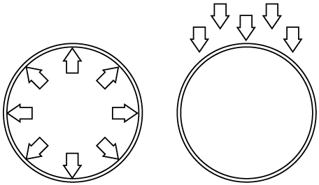
Standard Laying Conditions
ANSI/AWWA C150/A21.50 ANSI/AWWA C151/A21.51
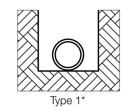
Flat-bottom trench.6 Loose backfill. (Not recommended for 14" and larger pipe.)
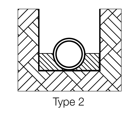
Flat-bottom trench.6 Backfill lightly consolidated to centerline of pipe.
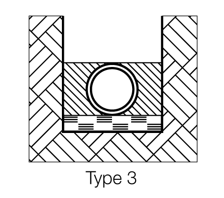
Pipe bedded in 4” minimum loose soil.7 Backfill lightly consolidated to top of pipe.
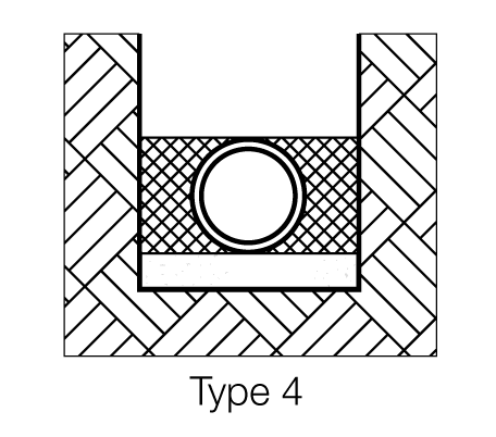
Pipe bedded in sand, gravel or crushed stone to depth of 1/8 pipe diameter, 4” minimum. Backfill compacted to top of pipe. (Approximately 80% Standard Proctor, AASHTO T-99.)
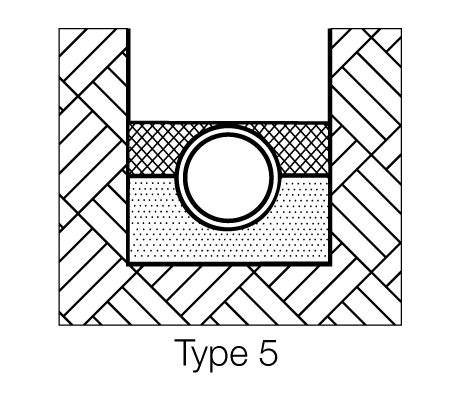
Pipe bedded to its centerline in compacted granular8 material, 4” minimum under pipe. Compacted granular or select material7 to top of pipe. (Approximately 90% Standard Proctor, AASHTO T-99.)
6 “Flat-bottom” is defined as undisturbed earth.
7 “Loose soil” or “select material” is defined as native soil excavated from the trench, free of rocks, foreign material and frozen earth.
8 Granular materials are defined per the AASHTO Soil Classification System (ASTMD3282) or the Unified Soil Classification System (ASTM D2487), with the exception that gravel bedding/backfill adjacent to the pipe is limited to 2" maximum particle size per ANSI/AWWA C600.