Flex-Ring Joint Pipe
Combining the sealing features of the time-proven Fastite joint and a boltless restrained connection, AMERICAN Flex-Ring joint ductile iron pipe provides flexible, easily assembled, positive restraint against endwise separation due to thrust.
Centrifugally cast for piping water, sewage and other liquids, Flex-Ring joint pipe may also be used in trenchless applications such as horizontal directional drilling and pipe bursting. With spigot ahead, the low-profile Flex-Ring bell assembles quickly and offers a smooth transition during pipe pull-back. AMERICAN offers a Flex-Ring pulling bell assembly specifically designed for this installation method.
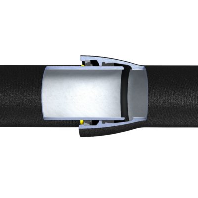
Flexible restraint for 4” through 12” sizes is provided by a beveled, welded-on ductile iron retainer ring plus a yellow painted ductile iron split flex-ring assembled behind the retainer ring. After the plain end of the pipe is assembled into the Flex-Ring bell, the split Flex-Ring is inserted and springs into the socket locking groove. The Flex-Ring is securely positioned behind the welded-on retainer ring and in the socket locking groove on the inside of the pipe bell.
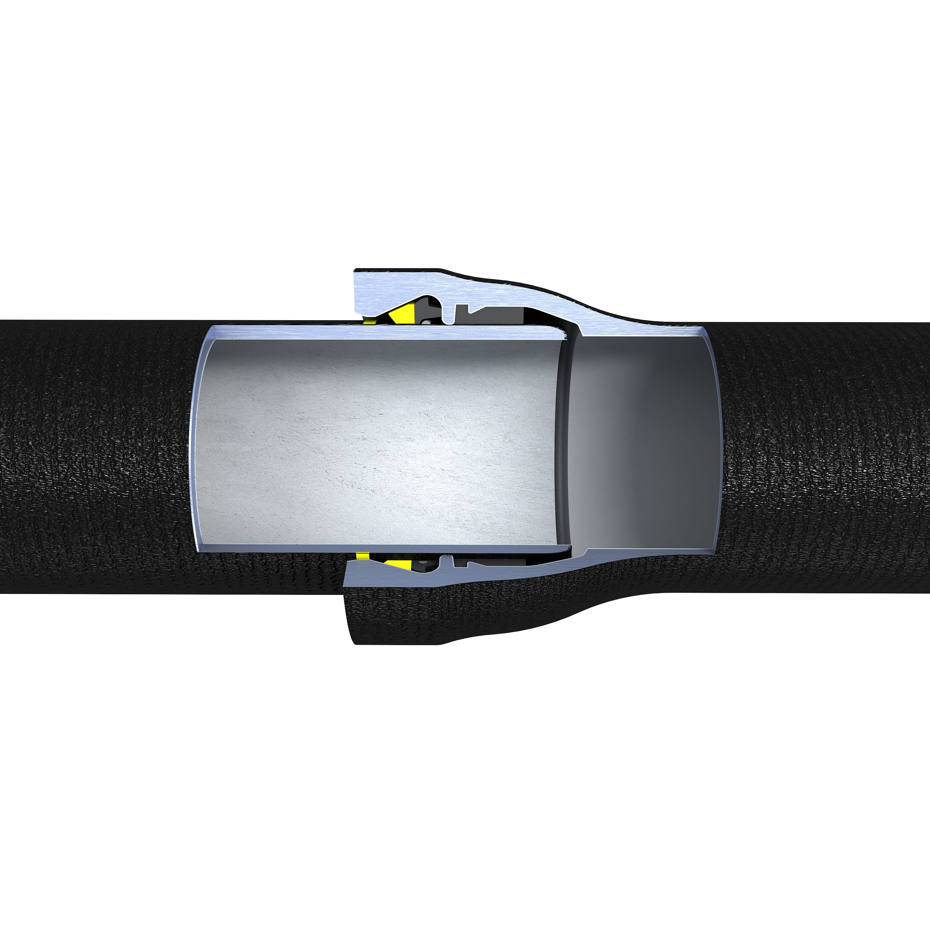
For 14” though 54” sizes, restraint is provided by a shop-applied weld bead and a rubber-backed ring containing yellow painted ductile iron segments. As the plain end of the pipe is fully assembled into the bell, the ductile iron segments automatically close on the pipe behind the weld bead. The enclosure of the segments between the weld bead, spigot and the sloped inner lip of the bell provides the flexible restraint.
The Flex-Ring joint’s liberal deflection allowance facilitates installation, decreases the number of necessary fittings and accommodates settlement.
The Flex-Ring joint is UL Listed and FM Approved in sizes 4" through 12" in all pressure classes and special thickness classes of ductile iron pipe. Fittings for use with Flex-Ring pipe are ductile iron and meet or exceed the applicable performance and manufacturing requirements of ANSI/AWWA C110/A21.10 or ANSI/AWWA C153/A21.53. Fittings in these sizes are also available in both bell-bell and bell-Flex-Ring spigot configurations for installation versatility and economy.
The only joint components needed to assemble the Flex-Ring Joint are a gasket and a single ring. No loose lugs, heavy wedges or rubber tubes are necessary. Also, there is no need to orient bells to ensure proper installation, although for convenience most installers orient the split locking ring ends in sizes 4” through 12” away from the very bottom of the joints.
Flex-Rings, Flex-Ring segments and retainer rings are manufactured of ductile iron compatible with pipe. Welds and weld beads (if used) are nickel-iron, proven desirably cathodic to the ductile iron pipe, and welding is performed using welders qualified to produce high-quality, dependable welds.
Field closures or other restraint can normally be securely made by using AMERICAN’s Fast-Grip gasket, available in 4" through 30" sizes. The Fast-Grip gasket restraint closure is UL Listed and FM Approved for use in Flex-Ring bells in 4" to 16" sizes. Field closures or other restraint in 14" to 36" sizes can also be made in Flex-Ring bells only by using AMERICAN’s Field Flex-Ring.

14 Inch through 54 Inch AMERICAN Flex-Ring Joint Design Shown Below