
Pressure Classes
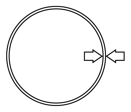
Pressure classes are defined as the hydrostatic water working pressure of the pipe in psi. The thicknesses shown are adequate for the rated hydrostatic working pressure plus a surge allowance of 100 psi with a safety factor of 2.0 for that sum. Calculations result in net thicknesses and are based on a minimum yield strength in tension of 42,000 psi and 2.0 safety factor times the sum of working pressure and 100 psi surge allowance.
Thickness can be calculated for rated hydrostatic working pressure and surges other than the above by use of equation 1 in ANSI/AWWA C150/A21.50.
AMERICAN ductile iron pipe is available for hydrostatic working pressures greater than 350 psi – for special applications, contact AMERICAN.
Standard Pressure Classes
Wall Thickness and Nominal Wall Thicknesses
ANSI/AWWA C150/A21.50
These are standard pressure classes as given in AWWA C150 and C151. AMERICAN can furnish any thickness in between these standard thicknesses if deemed desirable for major projects.
| Size (in.) |
OD (in.) |
Pressure Class | ||||
|---|---|---|---|---|---|---|
| 150 | 200 | 250 | 300 | 350 | ||
| Nominal Thickness in Inches | ||||||
| 4 | 4.8 | - | - | - | - | 0.25 |
| 6 | 6.9 | - | - | - | - | 0.25 |
| 8 | 9.05 | - | - | - | - | 0.25 |
| 10 | 11.1 | - | - | - | - | 0.26 |
| 12 | 13.2 | - | - | - | - | 0.28 |
| 14 | 15.3 | - | - | 0.28 | 0.3 | 0.31 |
| 16 | 17.4 | - | - | 0.3 | 0.32 | 0.34 |
| 18 | 19.5 | - | - | 0.31 | 0.34 | 0.36 |
| 20 | 21.6 | - | - | 0.33 | 0.36 | 0.38 |
| 24 | 25.8 | - | 0.33 | 0.37 | 0.4 | 0.43 |
| 30 | 32 | 0.34 | 0.38 | 0.42 | 0.45 | 0.49 |
| 36 | 38.3 | 0.38 | 0.42 | 0.47 | 0.51 | 0.56 |
| 42 | 44.5 | 0.41 | 0.47 | 0.52 | 0.57 | 0.63 |
| 48 | 50.8 | 0.46 | 0.52 | 0.58 | 0.64 | 0.7 |
| 54 | 57.56 | 0.51 | 0.58 | 0.65 | 0.72 | 0.79 |
| 60 | 61.61 | 0.54 | 0.61 | 0.68 | 0.76 | 0.83 |
| 64 | 65.67 | 0.56 | 0.64 | 0.72 | 0.8 | 0.87 |