Innovation Drives Iron Pipe Joint Technology
Water and Wastewater
This also appeared in the September 2019 Opflow.
By Maury D. Gaston, manager of Marketing Services for AMERICAN Ductile Iron Pipe and AMERICAN SpiralWeld Pipe
The United States recently celebrated its centennial year of standards for engineering products. Today’s American National Standards Institute (ANSI) dates to 1918, and in collaboration with the AWWA, it and other organizations produced a standard for iron pipe in 1926. This and other standards for products and processes are major reasons North America has the world’s finest municipal water systems in the world.
Development, innovation, and improvement is essential for a successful and long-lasting product. Although iron pipe has innovated in many ways, such as the improvement from gray iron to ductile iron, its joint technology, particularly restrained joint development, has been transformative. From leather gaskets, jute joints, labor-intensive cast-iron bolts and heavy glands to boltless, flexible, restrained joints that deflect and telescope today, iron pipe joint innovation and technology is substantial and impressive, particularly seismic and storm-resistant joint technology.
These developments are important, because more than 1.2 million miles of water main are known to be in service in the United States today. According to the landmark 2010 AWWA report Buried No Longer, 64 percent of those 1.2 million miles is made of iron pipe.
Iron Pipe Joint Development
The first cast iron pipe joints were flanged and used various materials, including leather, to seal the joint. According to the Ductile Iron Pipe Research Association’s Handbook of Ductile Iron Pipe, the bell and spigot joint was developed in 1785 and employed through the 1950s. The bell and spigot joint has a raised lip on the end of the spigot, and the annular space between the bell and the spigot was stuffed with jute and filled with various sealing materials selected by the user. In 1919, the Simplex joint was developed to replace rigid flanged joints and was first used in the petroleum industry in Texas. It resembled today’s mechanical joint, but what is today’s loose gland was then integral with the pipe. The use of rubber as a jointing material had been in practice in England since the third quarter of the 19th century, and its adoption in the United States hastened the spread of the mechanical joint with its separate follower gland to compress the rubber gasket.
The continued advancement of rubber technology made possible the ball and socket joint. This includes a machined ball that fits into a machined socket with a bolted retaining gland holding them together yet allowing 15 degrees of rotational flexibility. Elementary ball and socket joint designs date to 1930 and represent significant innovation and product development for their time. These flexible and durable joints made possible submerged crossings of rivers and other bodies of water not previously possible, thereby supporting economic development.
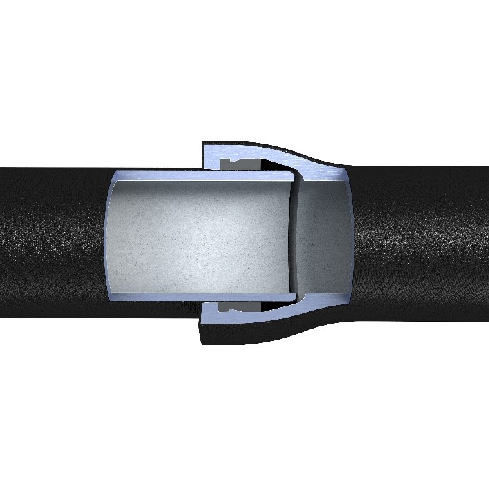
A breakthrough innovation in joint technology involved the elimination of bolts and assembly components, and on July 4, 1961, US Patent Number 2,991,092 was issued for the Fastite push-on rubber gasket joint, as shown in Figure 1. These push-on joints use a dual-durometer gasket with a stiff ring to hold the gasket in place against insertion loads and a softer, fatter section to provide the leak-free seal. The push-on gasket soon supplanted the bolted mechanical joint for virtually all underground pipe-to-pipe connections and remains the most common joint today for unrestrained and restrained joints.
Restrained Joint Innovation and Development
Thrust to be resisted is the product of pressure and cross-sectional area. Variations in the resultant thrust are proportional to the degree of the bend in the pipeline. Resultant thrust is countered by friction between the pipe and its surrounding environment. Factors contributing to the frictional resistance include primarily the coefficient of friction between the soil and pipe and the depth of backfill above the pipe. The objective of thrust restraint systems is to connect together with sufficiently strong joints a long enough length of pipe to engage with the surrounding soil so thrust from internal water pressure and surges can be more than counter-balanced. One well-accepted method of determining that length is offered by the Ductile Iron Pipe Research Association, and the easy-to-use program is available on-line at www.dipra.org.
Aside from thrust blocks and rigid flanged joints, the earliest restraint systems used threaded tie rods connecting each joint. These tie rods were expensive, labor intensive, and subject to loosening over time. The desire for an alternative resulted in the development of self-restraining joints. Flanged joints met that description, but their rigidity subjected them to bending moment forces often resulting in unintended consequences.
Just as unrestrained joint development began with bolts and labor and advanced to boltless products, so did restrained joint development. An iteration in the early 1960s used a push-on gasket inside a bell having a nonsealing flange and bolt holes. A follower gland with bolt holes was placed over the barrel of the connecting spigot. A substantial alloy bar was welded to the spigot barrel against which the loose follower gland engaged. Heavy bolts between the follower gland and the nonsealing flange ensured restraint. This was an improvement over flanged joints, and strong positive restraint was accomplished. On the other hand, this configuration was costly, heavy, labor-intensive, and required significant preconstruction planning and design.
Product development and innovation efforts now turned toward removing bolts and adding flexibility. This was accomplished with deeper bells having a cross section that accepted a locking wedge and mated against a weld-ring on the pipe spigot. The bolts were gone, and reasonable flexibility was introduced. Conventional push-on gaskets were also used. Product development progressed from the smaller through the larger diameters. The combination of strength and joint flexibility allowed this generation of restrained joints to be used in moderate-profile water crossings in place of the more expensive ball and socket pipe and has more recently been introduced to horizontal directional drilling applications.
At this stage of restrained joint development, bolts had been designed out, deflection had been designed in, and innovative engineers turned their attention to welding and field adaptability. By vulcanizing high-strength, hardened steel wedges with serrated teeth into push-on gaskets, the industry was able to combine joint restraint; joint deflection; boltless, easy, and fast assembly; and field adaptability into a completely restrained joint product. A further innovation was the production of these gaskets in bright colors to distinguish them from conventional, black, nonrestrained gaskets.
At this point, restrained joint innovation had progressed from heavy, bolted, rigid, expensive, pre-engineered, and time-consuming assemblies to standard-weight, boltless, flexible, affordable, field-adaptable, and easily-assembled connections. To make it even better, some brands are available on valves, bringing additional value to additional components of the water system.
Seismic and Storm-Resistant Joints
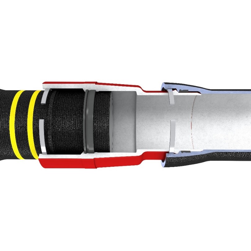
In the past few years, the water utility industry has focused on becoming better prepared for seismic and storm-related infrastructure threats. At the 2017 AWWA Water Infrastructure Conference in Houston, I presented an earthquake and storm-resistant joint system for ductile iron pipe, valves, and fire hydrants. This restrained joint provides up to 8 degrees of deflection in all radial directions and a range of motion of 4.8 inches longitudinal expansion or contraction. Endwise strength of this joint assembly ranges from 102,000 pounds for 6 in. to 408,000 pounds for 24 in. The joint cross-section is shown in Figure 2.
Several brands of seismic and storm-resistant joint systems have been tested in the Geotechnical Lifelines Large Scale Testing facility at Cornell University and met or surpassed the requirements of ISO 16143: Earthquake- and Subsidence-Resistant Design of Ductile Iron Pipelines. One manufacturer offers this seismic and storm-resistant joint for pipe, valve, and hydrant products. The use of seismic and storm-resistant joints for fire hydrants, isolation gate valves, and ductile iron pipe within areas of seismic risk, and the use of conventional restrained and flexible joints for ductile iron pipe and valves outward from a fault line, will provide a level of resiliency, dependability, and sustainability for public water supply and fire protection systems not otherwise available.
A Lasting Legacy
The history of iron pipe joint development chronicled here is one of increasing performance, efficiency, and consistent innovation. Today’s ductile iron pipe joints employ the latest technology and on-going innovation to provide secure and dependable joint and restraint performance for today’s water, wastewater, and fire protection infrastructure. These pipe joints are boltless, easy-to-assemble, flexible, telescope, and have tremendous thrust capacity. Ductile iron pipe and its modern, innovative, and sophisticated joint technology provides resilience in the most demanding environments. Additional innovation has occurred with coatings involving zinc and two-dimensional risk-based corrosion analysis, but those are complete topics in their own right and for another column.
