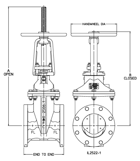
Standard Dimensions
| Size (in.) |
Series 2500 | Series 2500-1 | ||||||
|---|---|---|---|---|---|---|---|---|
| 2" | 2-1/2" | 3" | 4" | 6" | 8" | 10" | 12" | |
| A (valve open) /- 1/4 |
13.62 | 16.78 | 18.12 | 23.47 | 30.97 | 38.16 | 48.41 | 53.66 |
| B (valve closed) /- 1/4 |
11.5 | 14.12 | 14.94 | 19.12 | 24.59 | 29.91 | 38.16 | 41.78 |
| End to End - FL/FL (Class 125) |
7 | 7.5 | 8 | 9 | 10.5 | 11.5 | 13 | 14 |
| End to End - FL/FL (Class 250) |
N/A | N/A | 11.12 | 12 | 15.88 | 16.50 | 18 | 19.75 |
| Handwheel Diameter |
8 | 8 | 8 | 10 | 12 | 14 | 16 | 16 |
NOTES
- 3" through 12" valves meet or exceed requirements of ANSI/AWWA C515.
- Valve may be ordered in configurations that are UL Listed and FM Approved.
- 250 psig rated working pressure.
- Fusion-bonded epoxy coating meets or exceeds requirements of ANSI/AWWA C550.
- Bolt patterns of class 125 flanged ends are in accordance with ANSI/AWWA C110/A21.10 (ASME/ANSI B16.1 class 125).
- Class 250 flanged ends are in accordance with ASME B16.1, class 250 for cast iron flanges.
- 4" through 12" valves are certified to ANSI/NSF Standard 61.
- Open direction is specified by the customer.