Ductile Iron Pipe Icon
Restrained Joint Pipe

AMERICAN Flex-Lok - Ball Joint Pipe

AMERICAN Flex-LokTM Pipe incorporates a very flexible ball-and-socket type joint for use in such installations as subaqueous pipeline construction. The provision for significant changes in alignment, with available joint deflections of 25° for sizes 4”-12” and 15° for sizes 14”-54” in any direction, and the rugged features of AMERICAN Flex-Lok Pipe make it especially adaptable to the most difficult installations. This rugged joint configuration has an excellent record of performance, and under some of the toughest installation conditions, it has provided long life and trouble-free service. Economy and dependability have been proven in many installations under widely varying conditions.

AMERICAN Flex-Lok Boltless Ball Joint Pipe — manufactured in 4”-54” 1 sizes2 — is a rugged, boltless, flexible joint pipe designed and manufactured to assure the greatest economy in installation with maximum performance and reliability. This ductile iron pipe meets all applicable requirements of AWWA C151 and is designed to withstand severe installation and service conditions encountered in river crossings, treated wastewater outfall lines, water supply intakes, swamps, floodlands and rugged terrain where significant joint deflection may be required.

AMERICAN Flex-Lok Boltless Ball Joint Pipe provides variable deflection up to at least 15°, and the joint may be deflected to metal binding position at maximum deflection without harm to the pipe or joint components. This is a result of the unique design and functionality of the pipe and joint components. In sizes 4”-12”, the configuration incorporates the additional flexible restraint provided by AMERICAN’s Flex-Ring joint, which cumulatively results in greater joint deflection capabilities, up to 25°.

Spherical Socket

The spherical socket of the AMERICAN Flex-Lok joint is cast of ductile iron and is accurately machined to accommodate the ball of the adjoining pipe. The thick wall and bell section provides superior strength to minimize the stresses resulting from installation and service conditions.

The Flex-Lok joint gasket recess in the socket is designed and manufactured to provide easy insertion and positive seating of the gasket to avoid displacement during assembly and for constant compression of the gasket through the entire range of deflection of the assembled joint.

Spherical Ball

The ball end of the AMERICAN Flex-Lok joint is accurately machined to fit into the adjoining pipe socket and to provide constant compression of the gasket through the entire range of deflection of the assembled joint.

The inside surface of the ball is shaped so that the waterway will not be significantly obstructed at any angle of joint deflection.

Flex-Lok Gasket

The AMERICAN Flex-Lok joint uses the basic dual hardness gasket design of the AMERICAN Fastite joint that has been proven with millions of joints over approximately 55 years. Designed to provide maximum sealability, the Flex-Lok gasket is manufactured to AMERICAN’s rigid specification to assure controlled dimensional and material properties.

The snug fit of the gasket in the socket cavity, the design of the socket buttress and the hard section of the gasket act to restrain the gasket from dislodging during assembly.

Locking Systems

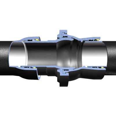
Two types of locking systems are used to prevent longitudinal joint separation of the AMERICAN Flex-Lok joint, depending on pipe size. In the 4”-24” sizes, the locking system employs a substantial external locking ductile iron gland and sizes 4”-12” also use the proven positive joint restraint system of the Flex-Ring joint. Both the spherical socket component and spherical ball component of the Flex-Lok joint in this size range have a Flex-Ring joint that is preassembled at AMERICAN. For 30”- 54” sizes, the joint is restrained with a ductile iron retainer ring fitted into a mating groove inside the heavy-section bell.

4"-24" Flex-Lok Pipe Joint

The locking gland of the 4”-24” AMERICAN Flex-Lok joint is cast of ductile iron. The gland has internal lugs that interlock with external lugs on the bell.

The lugs on the gland are passed between and beyond the lugs on the bell periphery, and the gland is then rotated to lock the joint and prevent separation.

All 4”-24” AMERICAN Flex-Lok Ball Joint Pipe is prepared for shipment to the job site with the locking gland strapped to the ball. These straps must be removed to free the gland for assembly. The 4”-12” configuration has a preassembled Flex-Ring joint both directly adjacent to the spherical socket and spherical ball. The locking gland is also shipped strapped to the ball.

A steel wedge with a welded-on threaded stud is provided for each 4”-24” AMERICAN Flex-Lok joint. One wedge is placed into the space between two lugs and bolted into position. This wedge provides a positive lock to prevent gland rotation after assembly.

30"-54" Flex-Lok Pipe Joint

A split retainer ring manufactured of ductile iron is fitted into a mating groove inside the heavy bell section, providing restraint against longitudinal joint separation in the 30”-54” sizes. This ring is shipped strapped to the ball. These straps must be removed to free the ring for assembly. After the ring is fitted into the groove inside the bell, a locking clip, held in place by a stainless steel spring, is inserted into the space between the ends of the ring to securely lock it into the groove.

Joint Lubricant

Special AMERICAN Joint Lubricant for underwater installation is furnished with each order to provide ample lubrication for assembly and joint flexing. This special lubricant is different from regular Fastite lubricant and is insoluble, non-toxic, will impart no taste or odor to the conveyed liquid and will not have a deleterious effect on the rubber gasket.

AMERICAN Flex-Lok Ball Joint Pipe is centrifugally cast in laying lengths shown under Standard Dimensions with the same standard outside diameters as AMERICAN Fastite or Mechanical Joint Pipe, thus simplifying tie-in connections by allowing the use of standard fittings.

AMERICAN Flex-Lok Ball Joint Pipe may be furnished with any of the coatings and linings described in Section 11. Unless otherwise specified, the pipe is normally furnished with an asphaltic coating on the exterior and with the interior cement lined per AWWA C104.

1.) The spherical ball and socket ends of 54” Flex–Lok pipe are fastened to the barrels of the pipe with a Fastite gasket and locking ring arrangement instead of threads.

Read More
contact sales

Standard Dimensions

4"–12"

Size
(in.)

Laying Length1
(ft.-in.)

Working
Pressure2
(psi)

T
Wall
Thickness3
(in.)

Nominal Weight in Pounds

Nominal Underwater Weight Per
Length Incl. Joint Materials4

Per Pipe
Length

Per Length
Incl. Joint
Materials

Per Foot
Incl. Joint
Materials

Full of Air
(lb.)

Full of Water
(lb.)

4

21’-6"

250

0.41

450

480

22.3

311

427

6

21’-7"

250

0.43

680

720

33.4

370

638

8

21’-8"

250

0.45

945

1000

46.2

396

886

10

21’-7-5/8"

250

0.47

1265

1325

61.2

418

1178

12

21’-8-5/8"

250

0.49

1565

1665

76.7

377

1481

14" & 18"

Size
(in.)

Laying Length1
(ft.-in.)

Working
Pressure2
(psi)

T
Wall
Thickness3
(in.)

Nominal Weight in Pounds

Nominal Underwater Weight Per
Length Incl. Joint Materials4

Per Pipe
Length

Per Length
Incl. Joint
Materials

Per Foot
Incl. Joint
Materials

Full of Air
(lb.)

Full of Water
(lb.)

14

20’-6"

250

0.51

1760

1880

91.7

193

1615

18

20’-6"

250

0.535

2425

2610

127.3

-1295

2245

16" & 20"

Size
(in.)

Laying Length1
(ft.-in.)

Working
Pressure2
(psi)

T
Wall
Thickness3
(in.)

Nominal Weight in Pounds

Nominal Underwater Weight Per
Length Incl. Joint Materials4

Per Pipe
Length

Per Length
Incl. Joint
Materials

Per Foot
Incl. Joint
Materials

Full of Air
(lb.)

Full of Water
(lb.)

16

22’-1"

250

0.52

2560

2719

124

337

2335

20

22’-3"

250

0.54

3445

3681

166

77

3160

24" - 48"

Size
(in.)

Laying Length1
(ft.-in.)

Working
Pressure2
(psi)

T
Wall
Thickness3
(in.)

Nominal Weight in Pounds

Nominal Underwater Weight Per
Length Incl. Joint Materials4

Per Pipe
Length

Per Length
Incl. Joint
Materials

Per Foot
Incl. Joint
Materials

Full of Air
(lb.)

Full of Water
(lb.)

24

22’-7"

250

0.565

4557

4636

206

-7045

3960

30

22'-4 5/8"

250

0.63

6666

6749

302

-1862

5252

36

22'-11 15/16"

250

0.73

9675

9787

426

-2943

7934

42

24'-2 5/16"

250

0.83

13871

13934

596.1

-4661

10190

48

23-6 1/4"

250

0.93

17347

17435

717

-7785

11931

54"

Size
(in.)6

Laying Length7
(ft.-in.)

Working
Pressure2
(psi)

T
Wall
Thickness8
(in.)

Nominal Weight in Pounds

Nominal Underwater Weight Per
Length Incl. Joint Materials4

Per Pipe
Length

Per Length
Incl. Joint
Materials

Per Foot
Incl. Joint
Materials

Full of Air
(lb.)5

Full of Water
(lb.)

54

23’-0"

250

1.05

24000

24150

1050

-3125

20950

Technical Data

4"-12"

Size
(in.)

A
(in.)

N
(in.)

Joint Materials
Weight in Pounds

Lubricant
Pounds
Per Joint

Maximum
Joint
Deflection

Maximum
Safe
End Pull
in Tons9

Gland

Gasket

Locking
Wedge

Complete
Set

4

4.80

11.79

27

1

1

29

0.09

25°

21

6

6.90

13.91

37

1

1

39

0.12

25°

35

8

9.05

16.38

50

1

2

53

0.16

25°

49

10

11.10

18.84

67

1

3

71

0.27

25°

63

12

13.20

21.56

89

1

3

93

0.40

25°

76

14"-18"

Size
(in.)

A
(in.)

N
(in.)

Joint Materials
Weight in Pounds

Lubricant
Pounds
Per Joint

Maximum
Joint
Deflection

Maximum
Safe
End Pull
in Tons9

Gland

Gasket

Locking
Wedge

Complete
Set

14

15.30

24.43

115

2

3

120

0.50

15°

90

18

19.50

29.70

181

3

4

188

0.75

15°

110

16" & 20"

Size
(in.)

A
(in.)

N
(in.)

Joint Materials
Weight in Pounds

Lubricant
Pounds
Per Joint

Maximum
Joint
Deflection

Maximum
Safe
End Pull
in Tons9

Gland

Gasket

Locking
Wedge

Complete
Set

16

17.40

26.78

140

3

4

147

0.60

22.5°

100

20

21.60

32.59

210

4

4

218

0.90

22°

119

24" - 48"

Size
(in.)

A
(in.)

N
(in.)

Joint Materials
Weight in Pounds

Lubricant
Pounds
Per Joint

Maximum
Joint
Deflection

Maximum
Safe
End Pull
in Tons9

Retaining Ring

Gasket

Spring/Clip

Complete
Set

24

25.80

33.82

14

5

1

20

1.10

21°

130

30

32.00

40.57

17

6

1

24

1.6

20°

225

36

38.30

48.43

35

8

1

44

2.2

19°

255

42

44.50

57.48

53

10

1

64

2.7

19°

305

48

50.80

64.45

77

10

1

88

3.5

19°

350

54"

Size
(in.)

A
(in.)

N
(in.)

Joint Materials
Weight in Pounds

Lubricant
Pounds
Per Joint

Maximum
Joint
Deflection10

Maximum
Safe
End Pull
in Tons9

Gland

Gasket

Locking
Wedge

Complete
Set

54

57.56

73.37

121

22

2

145

4.7

15°

450

Laying Lengths

4"-12"

Size
(in.)

L.L.
Maximum
Laying
Length5
(ft.-in.)

O.L.
Maximum
Overall
Length6
(ft.-in.)

A
(in.)

B
(in.)

Bell Weight
(lb.)

Ball Weight
(lb.)

4

21’-6"

21’-9 1/4"

1.38

1.77

55

41

6

21’-7"

21’-10 1/4"

1.38

2.01

72

61

8

21’-8"

21’-11 3/4"

1.42

2.34

99

88

10

21’-7-5/8"

21’-11 1/2"

1.42

2.61

143

123

12

21’-8-5/8"

22’-1"

1.42

2.91

184

169

14"-18"

Size
(in.)

L.L.
Maximum
Laying
Length11
(ft.-in.)

O.L.
Maximum
Overall
Length12
(ft.-in.)

A
(in.)

B
(in.)

Bell Weight
(lb.)

Ball Weight
(lb.)

14

20’-6"

20’-11 3/4"

1.73

3.32

177

183

18

20’-6"

20’-11 5/8"

1.73

3.87

277

297

16" & 20"

Size
(in.)

L.L.
Maximum
Laying
Length11
(ft.-in.)

O.L.
Maximum
Overall
Length12
(ft.-in.)

A
(in.)

B
(in.)

Bell Weight
(lb.)

Ball Weight
(lb.)

16

22'1 9/16"

22' 6 5/8"

1.73

3.58

312

290

20

22’3 5/16"

22’9 1/2"

2.01

4.16

505

420

24" - 48"

Size
(in.)

L.L.
Maximum
Laying
Length11
(ft.-in.)

O.L.
Maximum
Overall
Length12
(ft.-in.)

A
(in.)

B
(in.)

Bell Weight
(lb.)

Ball Weight
(lb.)

24

22’7 1/8"

23’1 7/8"

4.82

4.68

751

625

30

22'4 5/8"

23'3 1/4"

4.81

5.78

1320

1015

36

22'11 15/16"

24' 1/4"

5.88

6.41

2100

1640

42

23'4 1/2"

24' 10 1/4"

6.74

7.76

3292

2455

48

23'6 1/4"

24' 10 5/8"

7.73

8.69

4412

2987

54"

Size
(in.)

L.L.
Maximum
Laying Length7
(ft.-in.)

O.L.
Max. Overall
Length12
(ft.-in.)

A
(in.)

B
(in.)

Bell
Weight
(lbs.)

Ball
Weight
(lbs.)

54

23’-0"

24’-7 1/2"

9.50

9.97

5875

5440

1.) The laying lengths in the above tables are subject to trim pipe allowance in accordance with AWWA C151. Also, this is the fully homed or inserted laying length of 4”–48” Flex–Lok Pipe. In installations where 4”–48” joints are pulled or extended to metal–binding contact of joint locking members, some slight additional laying length will be gained as a function of the removal of joint assembly space. Contact AMERICAN when lengths are critical, or when it is necessary to locate ball joints at specific stations, etc. The joints will seal properly in any axial position from fully homed to fully extended and with any joint deflection angles up to the maximum rating.

2.) The working pressure is AMERICAN’s suggested standard water working pressure. Contact AMERICAN if higher working pressure is involved.

3.) Thicknesses correspond to Special Class 56. Check AMERICAN if pipe with other wall thickness is required.

4.) Does not include lining weight. Underwater pipe weights are for fresh water. Sea water is approximately 3% heavier than fresh water, and these weights should be adjusted accordingly for sea water installation.

5.) When full of air, pipe of this thickness will float unless weight is added. See Standard Cement Lining weights. Gross weight, including pipe, gland and lining, is painted on each length of Flex-Lok Pipe to aid in field calculations of actual buoyancy.

6.) Contact AMERICAN when lengths are critical, or when it is necessary to locate ball joints at specific stations, etc. The joints will seal properly in any axial position from fully homed to fully extended and with any joint deflection angles up to maximum rating when the joint is extended.

7.) Thicknesses correspond to Special Class 56 for 24”–54” sizes. Contact AMERICAN if pipe with other wall thickness is required.

8.) Contact AMERICAN for greater end pull requirements.

9.) The full deflection and laying length of 24”–54” joints is most readily obtained by fully extending the joints.

10.) The maximum laying length (and accordingly the maximum overall length) is subject to trim pipe allowance in accordance with AWWA C151. Also, this is the fully homed or inserted laying length of Flex–Lok pipe. In installations where joints are pulled or extended to metal–binding contact of joint locking members, some slight additional laying length will be gained as a function of the removal of joint assembly space. The joints will seal properly in any axial position from fully homed to fully extended and with any joint deflection angles up to the maximum rating.

11.) Overall Length (O.L.) equals Laying Length L.L. + A + B.

Product Line Information

Domestic Certification
Submittals
Pipe Manual
Project Mgt/Customer Service
Standards
Aerial view of iron pipes

Contact Sales

Reach out to our sales team for more product information.
contact sales

Today's Infrastructure Solutions in the U.S. and Around the Globe.

About Us